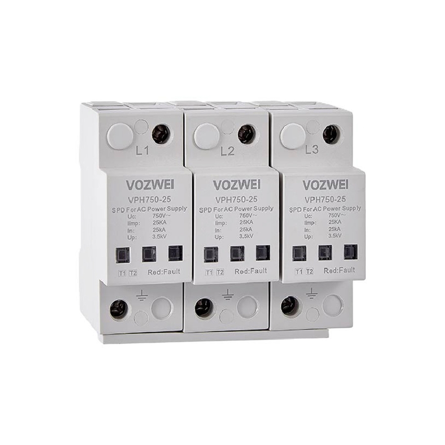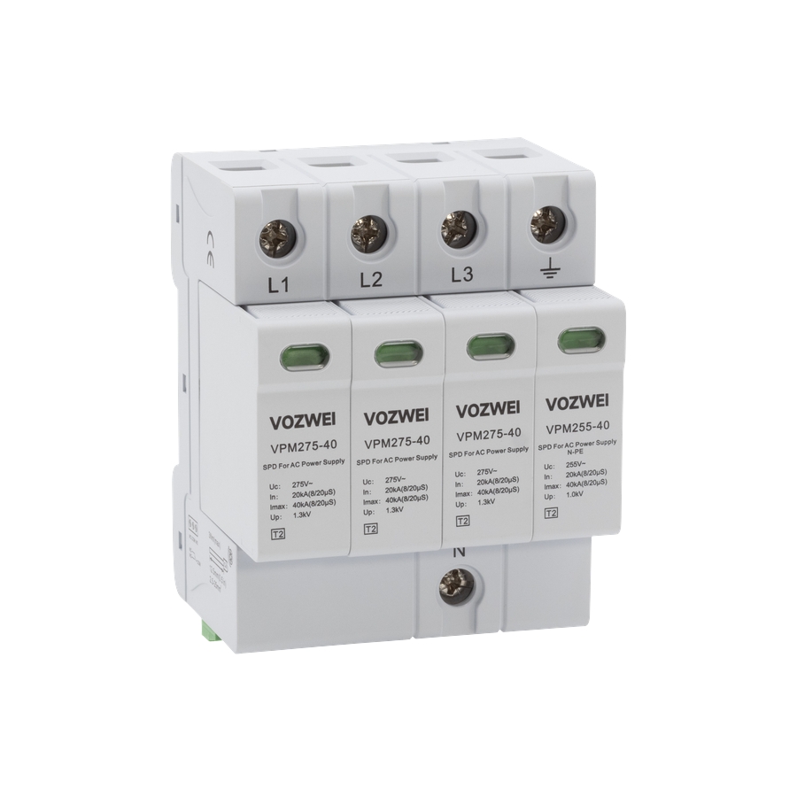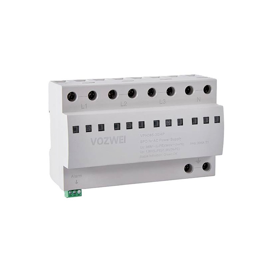
Application:
The VPH888 series are combined Type 1 + Type 2 surge protective devices (SPDs). Their integrated design provides coordinated two-stage protection within a single unit: high-energy impulse current (Iimp) discharge for primary protection at the LPZ0-1 boundary, followed by fine protection with low residual voltage. This makes them ideal, space-saving solutions for main power inlets and distribution boards in commercial, industrial, and critical infrastructure applications requiring maximum reliability against lightning and surge threats.
Technical parameters:
|
Model
|
VPH888-12.5/3P+1P(T1+T2)
|
|
SPD according to EN/IEC 61643-11
|
Type 1+2
|
|
Network
|
IT-TN
|
|
Protection mode
|
3+1 mode
|
|
Nominal operating voltage Un
|
AC 690 V 50/60 Hz
|
|
Max. continuous operating voltage Uc
|
AC 880 V 50/60 Hz
|
|
Impulse current Iimp (10/350 μs)
|
12.5 kA
|
|
Nominal discharge current In (8/20 μs)
|
20 kA
|
|
Max. discharge current Imax (8/20 μs)
|
80 kA
|
|
Voltage protection level Up
|
≤ 3.4 kV
|
|
Leakage current
|
≤ 20 μA
|
|
Response time
|
≤ 25 ns
|
|
Max. backup fuse
|
250 A gL/gG
|
|
Cross-sectional area
|
6 ~ 35 mm2
|
|
Stripping length terminals
|
12.5 mm
|
|
Tightening torque
|
3 N·m
|
|
Normal/Fault Indication
|
Green/Red
|
|
Remote signaling mode
|
RSC: Remote Signal contact, NC-COM-NO contact
|
|
Performances of remote signal contact
|
AC: 250 V/0.5 A; DC: 250 V/0.1 A, 125 V/0.2 A, 75 V/0.5 A
|
|
Remote cross-sectional area
|
Max. 1.5 mm2
|
|
Installation method
|
35 mm DIN rail
|
|
Housing material
|
PBT UL94-V0
|
|
Protection class
|
IP20
|
|
Operation temperature
|
-40 ℃ ~ +80 ℃
|
|
Relative humidity
|
≤ 95% (25 ℃)
|
|
Operating altitude
|
≤ 3000 m
|
|
Outline dimensions (without terminal)
|
90.0 mm × 72.0 mm × 77 mm (tolerance ± 1 mm)
|
|
Module pluggable
|
Pluggable
|
|
Internal protective devices
|
Built-in thermal tripping device
|
|
Short-circuit withstand capability
|
25 kArms
|
Selection guide:
|
Model
|
Un
|
Uc
|
Up
|
In
|
Imax
|
Protection mode
|
Operating Principle
|
Size
|
|
VPH888-12.5/3P+1P(T1+T2)
|
AC 690 V
|
AC 880 V
|
3.4 kV
|
20 kA
|
80 kA
|
L-PE
|
Figure1.9.1
|
Figure 1.10.1
|
Operating Principle: