Application:
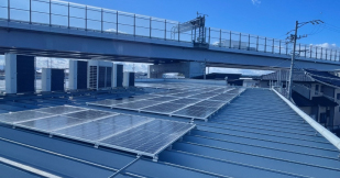
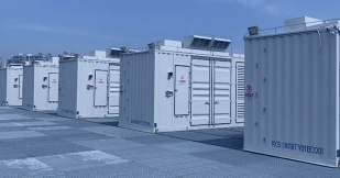
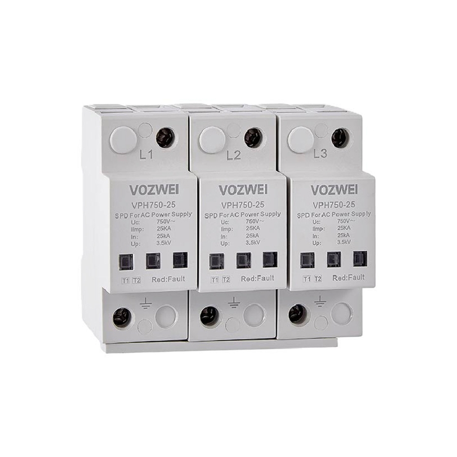
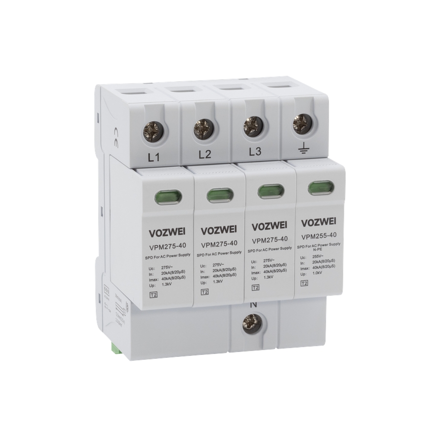
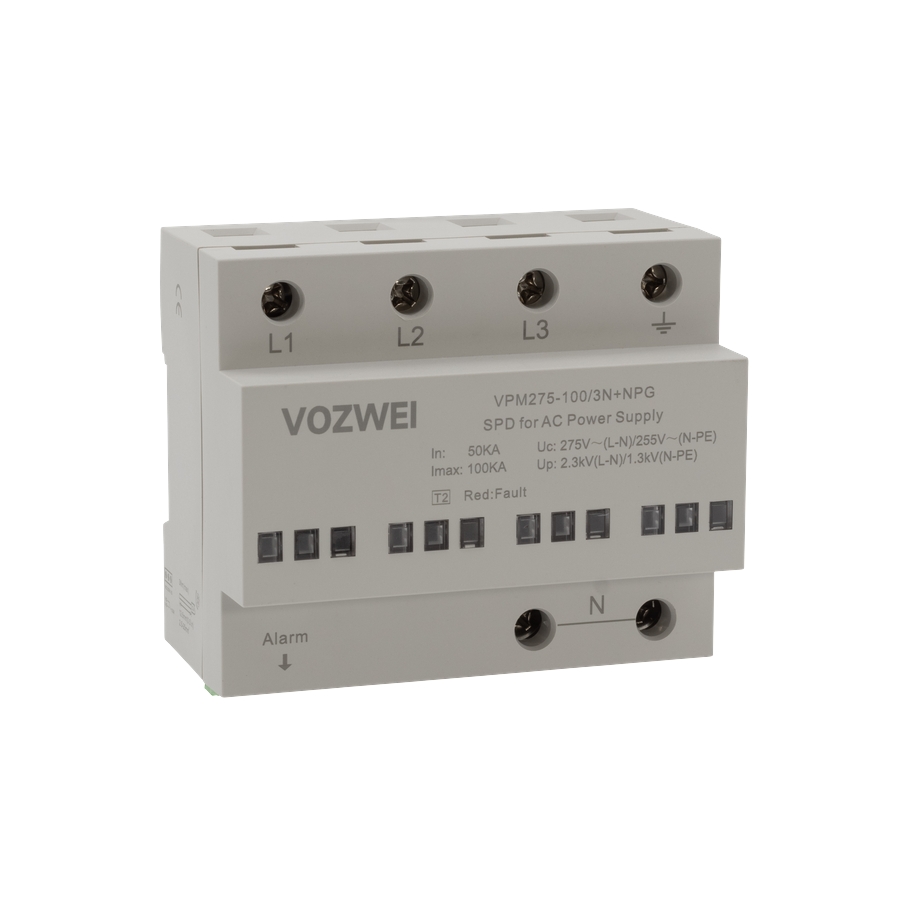
This product is a high-capacity, low-voltage surge protective device (SPD) designed for Type 1 (Class B) installation at the main power inlet of low-voltage distribution systems, located at the boundary between LPZ0 and LPZ1 zones. It protects sensitive electrical equipment against damage from direct lightning strikes and induced transient overvoltages.
Nomenclature:
VP □ □–□/□□
1 2 3 4 5
|
SN
|
Name
|
Specification, type code
|
|
1
|
Design code
|
VP
|
|
2
|
Product Series
|
H
|
|
3
|
Max. continuous operating voltage Uc
|
385: AC 385 V
|
|
4
|
Impulse current Iimp (10/350 μs)
|
30: 30 kA
|
|
5
|
Protection mode
|
2P: 2P; 3P: 3P; 4P:4P; 3N+NPE: 3N+NPE
|
Example: VPM275-40/3N+NPG → Uc: AC 275 V; Imax: 40 kA; Protection mode: 3N+NPG.
Technical parameters:
|
Model
|
VPH385-30/4P
|
|
SPD according to EN/IEC 61643-11
|
Type 1
|
|
Protection mode
|
L-PE & N-PE
|
|
Nominal operating voltage Un
|
AC 230/400 V 50/60 Hz
|
|
Max. continuous operating voltage Uc
|
AC 385 V 50/60 Hz
|
|
Impulse current Iimp (10/350 μs)
|
30 kA
|
|
Voltage protection level Up
|
≤ 1.9 kV
|
|
Response time
|
≤ 100 ns
|
|
Cross-sectional area
|
6 ~ 35 mm2
|
|
Stripping length terminals
|
12.5 mm
|
|
Tightening torque
|
3 N·m
|
|
Normal/Fault Indication
|
Green/Red
|
|
Remote signaling mode
|
RSC: Remote Signal contact, NC-COM contact.
|
|
Performances of remote signal contact
|
Max open circuit voltage: 300 V; Maximum load current: 100 mA; Node equivalent resistance: 50 Ω.
|
|
Remote cross-sectional area
|
Max. 1.5 mm2
|
|
Installation method
|
35 mm DIN rail
|
|
Housing material
|
UL94-V0
|
|
Protection class
|
IP20
|
|
Operating temperature
|
-40 ℃ ~ +80 ℃
|
|
Relative humidity
|
≤ 95% (25 ℃)
|
|
Operating altitude
|
≤ 3000 m
|
|
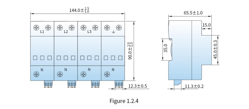
Outline dimensions (without terminal)
|
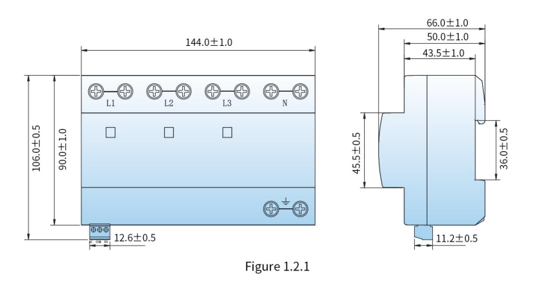
90 mm × 144 mm × 66 mm (tolerance ± 1 mm)
|
|
Internal protection device
|
The lightning protection unit has a built-in thermal trip device
|
|
External protection device
|
The incoming cables must be connected in series to the C circuit breaker with the rated current not exceeding 63 A.
|
Selection guide:
|
Model
|
Un
|
Uc
|
Up
|
In
|
Iimp
|
Protection mode
|
Operating Principle
|
Size
|
|
VPH385-30/2P
|
AC 230 V
|
AC 385 V
|
1.9 kV
|
30 kA
|
30 kA
|
L-PE & N-PE
|
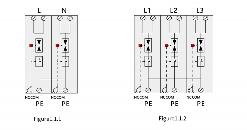
Figure 1.1.1
|
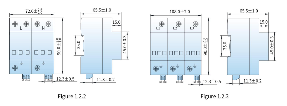
Figure 1.2.2
|
|
VPH385-30/3P
|
AC 230 V
|
AC 385 V
|
1.9 kV
|
30 kA
|
30 kA
|
L-PE
|
Figure 1.1.2
|
Figure 1.2.3
|
|
VPH385-30/4P
|
AC 230 V
|
AC 385 V
|
1.9 kV
|
30 kA
|
30 kA
|
L-PE & N-PE
|
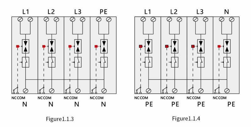
Figure 1.1.4
|
Figure 1.2.1
|
|
VPH385-30/3N+NPE
|
AC 230 V
|
AC 385 V
|
1.9 kV
|
30 kA
|
30 kA
|
L-N & N-PE
|
Figure 1.1.3
|
Figure 1.2.4
|
Operating Principle: